
A Roof Over Your Head
65 Days Until I Can Walk
A little more than two weeks into this project, and I have implemented ceiling textures and basic look up/down functionality.
In terms of features that I want my ray cast engine to support, these are more or less the final two. I would like to implement sky boxes, and multi-height walls at some point, but for now I am quite happy with what I have. It feels like the appropriate thing to do at this stage is to take a beat and begin refactoring the code. My initial intention with this project was to learn Rust and WebAssembly while producing educational content that may be helpful for other people. However, now I feel that I would also like to release the engine when finished so that other developers may use it to write and deploy games to the Internet.
If I really want to make this happen, then my code will need a major overhaul. At the moment everything is a pretty serious, tightly coupled mess, but a little love and care at this stage could do a lot to alleviate some of that technical debt. I will be working on this for the rest of the week.
Before that, however, let’s talk about implementing floor/ceiling textures and a look up/down mechanic.
Floor And Ceiling Textures
Rendering floors and ceilings is a symmetric process. If you can do one, then you can do the other with minimal modification to your code. We will focus on rendering floors first.
 .
.
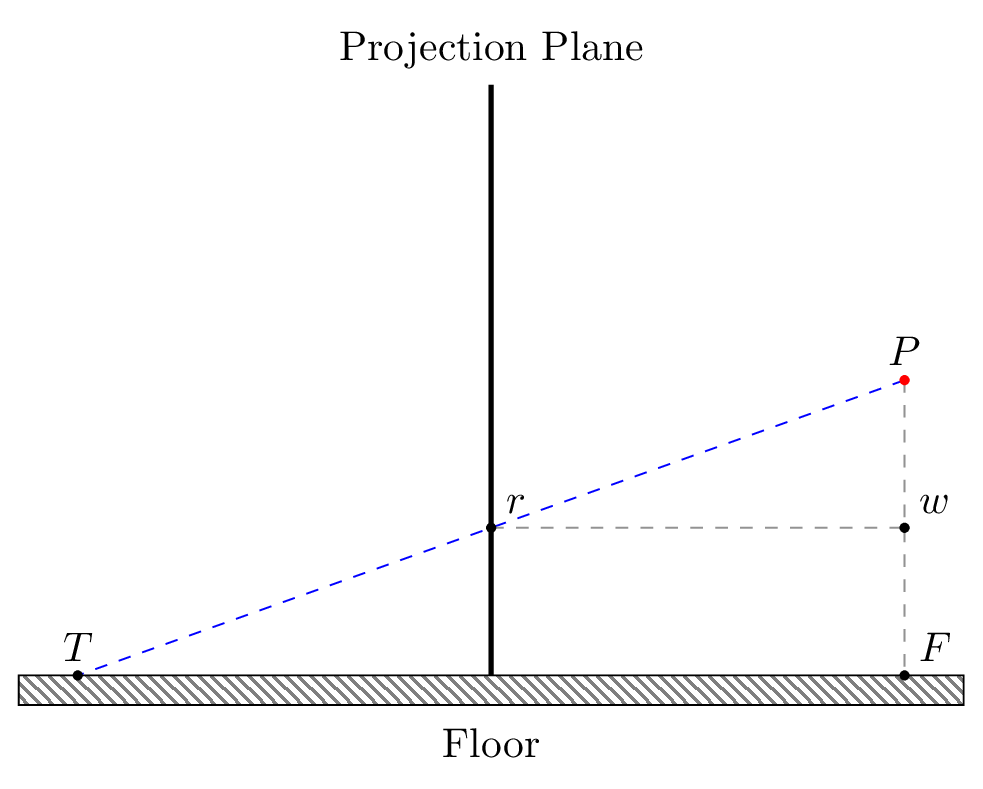
In order to render a floor, we fire a ray from the player’s eye, through the pixel \(r\) in the projection plane where we would like to apply a floor texture, and then out into the world. In the image above this ray is represented by the dashed blue line \(\overline{\rm PT}\). In order to work out where this ray strikes the ground, we must first determine how far it travels from the player before it strikes the ground. This distance is given by the line segment \(\overline{\rm TF}\).
We can work out the length of \(\overline{\rm TF}\) using similar triangles. We note that the triangle \(\triangle PTF\) is similar to \(\triangle Prw\) as \(\angle FPT = \angle wPr\) (same angle), \(\angle TFP = \angle rwP\) (right angles), and \(\angle FTP = \angle wrP\) (parallel line theorem).
Therefore, we can work out the length of \(\overline{\rm TF}\) by computing the length of \(\overline{\rm rw}\) and then scaling that value up by some ratio. We can work out the ratio by looking at the difference in size of sides \(\overline{\rm PF}\) and \(\overline{\rm Pw}\).
\(\overline{\rm PF}\) is simply the player’s height above the ground. \(\overline{\rm Pw}\) is the difference in the y-axis between the horizon and \(r\). Therefore we can compute the ratio required to scale \(\overline{\rm rw}\) as follows:
\[ratio = \frac{player height}{row - horizon}\]Given our ratio, we need to work out the length of \(\overline{\rm rw}\). But this is simply the distance between the player and the projection plane. This value is constant and can be worked out using the width of our projection plane, and the angle of the player’s field of view.
 .
.
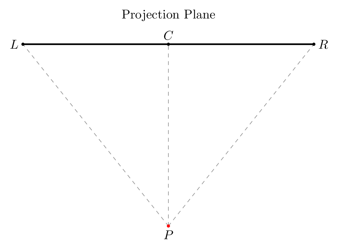
In the above diagram, the line segment \(\overline{\rm LR}\) represents the projection plane. Point \(P\) represents the player, and the line segment \(\overline{\rm PC}\) is the player’s perpendicular distance from the projection plane. The player’s field of vision is given by the angle \(\angle LPR\). This angle is defined by the engine as \(60^{\circ}\). The length of \(\overline{\rm LR}\) is also defined by the engine and is given the value 320.
We can therefore work out the lenght of \(PC\) using basic trigonometry. Recognizing that the angle \(\angle LPR\) is bisected by \(PC\) means that \(\angle RPC\) is \(30^{\circ}\). Given that \(C\) is the centre point of \(\overline{\rm LR}\), then \(\overline{\rm CR} = 320 \div 2 = 160\). \(PC\) is thus:
\[\overline{\rm PC} = \frac{160}{tan(30)} = ~277\]We know that \(\overline{\rm rw} = \overline{\rm PC}\). So we can now work out \(\overline{\rm TF}\) by doing the following:
\[\overline{\rm TF} = ratio \times 277\]Observe that:
- 277 is constant for all points, and
- There are only 100 possible values for ratio (the distance from the horizon to the bottom of the projection plane)
We can precompute all values of \(\overline{\rm TF}\) at compile time and store them in a lookup table, saving precious runtime cycles.
However, there is a small hitch in our maths so far. We have computed the straight-line distance from the player to a floor tile, which works for the centre row of the projection plane. However, similar to the issue with the fishbowl effect when casting rays for walls, rays to the left and right of the centre need to have their length adjusted for skew. Fortunately, we can actually use the same formula for correcting the fishbowl effect.
We therefore adjust the length of \(\overline{\rm TF}\) as follows:
\[\overline{\rm TF}_{adjusted} = \frac{\overline{\rm TF}}{cos\beta}\]Where \(-30^{\circ} \le \beta \le 30^{\circ}\) is the angle at which the ray is being cast.
Now that we know the length of our ray, we can determine its x and y displacement based on the direction the player is facing, given by the angle \(\alpha\).
\[\Delta x = \overline{\rm TF}_{adjusted} \times cos(\alpha)\] \[\Delta y = \overline{\rm TF}_{adjusted} \times sin(\alpha)\]This gives us where the ray would strike the ground if the player were standing at the point of origin \((0, 0)\) on the map. Obviously the player is unlikely to be standing at that spot. So the final \(xy\) coordinate of the ray where it strikes a tile \((T_x, T_y)\) is given by displacing \((\Delta x, \Delta y)\) by the current position of the player \((p_x, p_y)\):
\[T_x = p_x + \Delta x\] \[T_y = p_y + \Delta y\]From here on our process is the same as it was for walls. We first check to see if \((T_x, T_y)\) is out of bounds. If not then we get the texture code for the tile at that point and work out which column/row of the texture was struck by computing:
\[column = T_x \bmod 64\] \[row = T_y \bmod 64\]Where 64 is the size of a floor tile. We can now draw the pixel at that location in the texture to the screen.
The process for computing the ceiling texture is exactly the same, except that we compute the ratio a little differently. Instead of using the player’s height, we use the distance from the player’s head to the top of the wall. If we assume that our walls are 64 units high (which is quite typical) and our player is 32 units high (again, quite typical) then the ratio is the same for both floors and ceiling.
Look Up/Down
Implementing this mechanic is surprisingly simple. In fact, it is so simple, that I accidentally created the effect in the browser by making the canvas element too big.
Normally when we render with a ray caster, we assume that there is a horizon line running horizontally across the middle of the projection plane. Anything above the line is sky and anything below the line is floor. When we render walls, we centre them around this horizon line so that half their height is above the line, and the other half is below.
Implementing look up/down is as simple as shifting the horizon line. Moving it further down the projection plane creates a look up effect. Conversely, moving it up the plane creates a look down effect.
You can actually sort of see how this works if you repeat my little mistake and make the canvas too big (I set it to be 2048 pixels wide in the gif below). If I scroll the page up and down in the browser so I can see the bits that are offscreen, the effect is to make it look like the character is looking up and down.
To implement the effect in code, I replace my PROJECTION_PLANE_HORIZON constant with a variable horizon that can be set between 20 and 180, bounding how far the player can look up and down. There are then some sections of code that must be updated.
In the floor and ceiling texture functions, the length of a ray is computed using a ratio based on the player’s height, and the difference between the row index of the pixel being textured, and the horizon. This ratio must now use the variable horizon instead of the PROJECTION_PLANE_HORIZON.
When determining where to draw the walls, we compute wall height and then draw half the wall above the horizon and half below. This must now be updated to use the variable horizon.
We also use the horizon line to determine whether to draw a floor or ceiling texture if there is a transparent spot in the middle of a wall texture. Again, this decision depends on whether the transparent spot is above or below our new movable horizon.
With this done, we expose a function that allows you to shift the horizon line and bind this to some keys so the user can look up and down. My implementation currently uses the up and down arrows.
Et voila! Pseudo look up/look down. Obviously we aren’t really looking up and down in a 3D space, so cracks will appear in the facade if you look too closely. But this is enough to give our 2.5D world a little bit more depth.
Conclusion
Quite a long post today about texturing, but I felt that it was good to give as much detail as possible. I learned about floor and ceiling texturing from F. Permadi, of course, but I wanted to expand on his notes a little.
Tomorrow begins the great refactor, so let’s see how that goes.